How UART works and its Interface with Bluetooth
Devices equipped with Bluetooth technology support wireless point-to-point connections, as well as wireless access to LAN, mobile phone network, the Ethernet and home networking. The connectivity between two Bluetooth equipped devices is carried out as serial communication. Bluetooth technology delivers the received data and receives the data to be transmitted to and from a host system through a host controller interface (HCI). The most popular host controller interface today is either a UART or a USB link.
Now, even though we can use USB or UART, the most commonly used HCI is UART because of following reasons:
◦If UART is used software overhead is very less
◦Its highly cost effective.
A Universal Asynchronous Receiver and Transmitter (UART) is used for communication with serial input and serial output devices. Serial transmission reduces the cost and complexity of the wirings at the expense of speed, and for many applications this is a desired trade-off. The UART takes bytes of data and transmits the individual bits in a sequential fashion. At the destination, a second UART re-assembles the bits into complete bytes. Synchronization for the serial data stream is accomplished by adding start and stop bits to the transmit data to form a data character. Data integrity is insured by attaching a parity bit to the data character. The parity bit is checked by the receiver for any transmission bit errors.
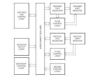
To a host system, the UART appears as an 8-bit input and output port that it can read from and write to. Whenever the host has data to be sent, it just sends these data to the UART in byte format (8-bit wide), whenever the UART receives data from another serial device it will buffer these data in its FIFO (again 8-bit wide), then it will indicate the availability of these data to the host through an internal register bit, or through a hardware interrupt signal.
Register Select is used to decode the address of register which the host wants to access. DataBus and Control Logic is how the host transmits and receive data to/from UART. There are several registers in UART. Some of them are TransmitHoldRegister(THR), Receive Hold Register(RHR) – both as name suggests is used to hold Transmitting and Receiving data. Then there is Interrupt Enable register used to enable/disable different kinds of Interrupts supported by UART. There are other registers used to control FIFO, Modem, Data format, etc. The Shift Registers are used to break the byte information for sequential transfer OR assemble the bits using FIFO to form Byte data.
Now that we understand the functionality of UART , lets see how it is interfaced with Bluetooth. Consider the following diagram
The host controller sends the data using D[7-0] channel and address using A[0-2] channel. The UART chip receives these data and using shift registers and FIFO , it converts into serial data. These serial bits will be then sent to Bluetooth Controller (Rx,Tx,CTS,RTS) and then transmitted via RF channel.
This is a brief overview of working of UART explained using SC16C650B and its interface with Bluetooth.
For more info visit: http://en.wikipedia.org/wiki/Universal_asynchronous_receiver/transmitter.
This post was originally posted by me on http://www.techyspot.com/2010/10/how-uart-works-and-its-interface-with-bluetooth/


Comments
Post a Comment
Please post comments here:-)